
- What a magnetic field is, and how to picture it using field lines
- How a straight wire, a circular loop and a solenoid each produce their own field pattern, and how to find its direction with the right-hand thumb rule
- Why a current-carrying conductor feels a push inside a magnetic field, and how Fleming’s left-hand rule tells you which way
- How the live, neutral and earth wires in your own house keep you safe, and what actually happens during a short circuit
1 Magnetic Field and Field Lines
You already know that a compass needle is really a tiny bar magnet: the end that points north is its north pole, and the end that points south is its south pole. Bring it near a real bar magnet and it swings around: like poles push each other away, unlike poles pull together. What actually reaches out and turns the needle, even though nothing touches it?
The region surrounding a magnet, in which the force of the magnet can be detected, is called a magnetic field.
Sprinkle iron filings around a bar magnet on a sheet of paper and tap the sheet gently: the filings do not scatter randomly, they line up in a clear pattern. Each filing becomes a tiny compass, turned by the field at its own location. Trace that pattern with a real compass, point by point, and you get smooth curved lines running from one pole to the other.
Magnetic field lines are the lines along which a free north pole would tend to move if placed in a magnetic field, the same lines the iron filings arrange themselves along.
Magnetic field is a quantity that has both direction and magnitude. The direction of the magnetic field is taken to be the direction in which a north pole of the compass needle moves inside it. That is why, by convention, field lines are drawn emerging from the north pole and merging at the south pole of a magnet, with arrows marked on them.

Direction
Outside the magnet, lines go N → S. Inside the magnet, they go S → N. So every field line is a closed loop.
Strength
Field lines crowded close together mean a stronger field; spread far apart means a weaker field.
They never cross
If two field lines crossed, the compass needle at that point would have to point in two directions at once, which is impossible.
“Why don’t two magnetic field lines intersect each other?” is a favourite 1-2 mark question. Always give the reasoning, the needle-would-point-two-ways argument, not just “they don’t.”
Students often say field lines go from south to north everywhere. They only do that inside the magnet. Outside the magnet, they always go from north to south.
2 Magnetic Field due to a Current-carrying Conductor
Magnets are not the only source of a magnetic field. Place a compass needle near a straight copper wire and pass current through it: the needle deflects, exactly as it would near a bar magnet.
Hans Christian Oersted (1777-1851) discovered by accident in 1820 that a compass needle got deflected when an electric current passed through a metallic wire placed nearby. Through this observation he showed that electricity and magnetism are related phenomena, and it opened the door to the radio, television and fibre optics that followed. The unit oersted, used for magnetic field strength, is named after him.
A long straight copper wire, two or three cells of 1.5 V each and a plug key are connected in series, and the straight wire is placed parallel to and over a compass needle. When the key is plugged in and the current flows from north to south in the wire, the north pole of the needle moves towards the east. When the cell connections are reversed, the current flows from south to north and the needle moves the opposite way, towards the west.
Conclusion: reversing the direction of the current reverses the direction of the magnetic field it produces.
2.1 Field around a straight current-carrying conductor
Pass a long straight wire through a hole in a horizontal piece of cardboard, sprinkle iron filings on the cardboard, and switch on the current. Tap the board gently: the filings arrange themselves into concentric circles centred on the wire.
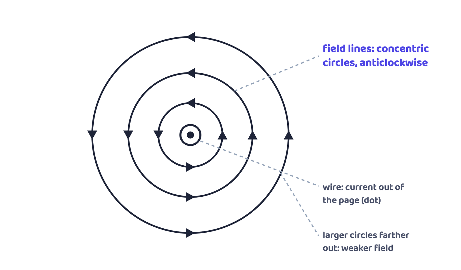
Two things change this pattern: increase the current, and the compass deflection at a fixed point increases: the field is stronger for a larger current. Move the compass farther from the wire with the current unchanged, and the deflection decreases: the field is weaker farther from the wire. Reverse the current, and the direction the needle deflects reverses too.
2.2 The right-hand thumb rule
Imagine holding a current-carrying straight conductor in your right hand so that the thumb points in the direction of the current. Your curled fingers then point in the direction of the magnetic field lines around it. This is the right-hand thumb rule, also called Maxwell’s corkscrew rule, since it matches the way a corkscrew turns as it is driven in the direction of the current.

Q. Current in a horizontal power line flows from east to west. What is the direction of the magnetic field at a point directly below it, and at a point directly above it?
Given: current direction: east → west
Find: field direction at points above and below the wire
Solution: Applying the right-hand thumb rule to the east-west current, the field circles the wire clockwise when viewed from the east end, and anticlockwise when viewed from the west end, true at any point above or below the wire.
2.3 Field due to a current through a circular loop
Bend the same straight wire into a circular loop and pass current through it. Every small section of the loop still produces circular field lines around itself, but because the whole loop curves round, those little circles overlap and add up. Near the wire the pattern still looks like circles; right at the centre of the loop, so many arcs overlap that the field lines there look almost straight.

A loop of wire wound round several times, instead of just once, is called a coil, and each single winding of it is called a turn.
2.4 Field due to a current in a solenoid
A solenoid is a coil of many circular turns of insulated copper wire, wound closely together in the shape of a cylinder.
The field pattern of a current-carrying solenoid looks just like that of a bar magnet: one end behaves as a north pole, the other as a south pole. Inside the solenoid, the field lines run parallel to its axis, which means the field there is the same at every point: it is uniform inside a solenoid.

Because the lines inside a long solenoid are parallel and equally spaced, they show what a uniform magnetic field looks like on paper: straight, parallel, equally spaced lines, all with arrows pointing the same way.

An electromagnet is formed when a piece of magnetic material such as soft iron, placed inside a current-carrying solenoid, gets magnetised by the strong field inside it.
3 Force on a Current-carrying Conductor in a Magnetic Field
A current-carrying conductor produces a field that pushes on a nearby magnet. Just as every force has an equal and opposite reaction force (Newton’s third law), the magnet must also push back on the current-carrying conductor.
It was the French scientist André-Marie Ampère (1775-1836) who first suggested that the magnet must exert an equal and opposite force back on the current-carrying conductor.
Hang a light aluminium rod between the poles of a horseshoe magnet, with the field pointing straight up, and pass current through the rod: the rod swings sideways. Reverse the current, and it swings the other way. Reverse the magnet’s poles instead, and it swings the other way again. The push is largest when the current and the field are exactly perpendicular to each other.
Fleming’s Left-Hand Rule: stretch the thumb, forefinger and middle finger of the left hand so that all three are mutually perpendicular (each one at right angles to the other two, like the corner of a box). If the forefinger points in the direction of the magnetic field and the middle finger in the direction of the current, then the thumb points in the direction of the force (motion) on the conductor.

Q. An electron enters a magnetic field at right angles to it, as in the textbook’s Fig. 12.14: the magnetic field points from left to right across the page, and the electron moves downward, from the top of the page towards the bottom. What is the direction of the force acting on the electron?
Given: magnetic field from left to right; electron moving downward (top to bottom of the page), at right angles to the field
Find: direction of the force on the electron
Solution: The conventional current direction is opposite to the direction of electron motion (electrons are negative), so here the current points upward, from the bottom of the page towards the top. Apply Fleming’s left-hand rule: forefinger along the field (to the right), middle finger along the current (upward). The thumb then points into the page, so the force on the electron is directed into the page.
Devices built on exactly this current-in-a-field push include the electric motor, the electric generator, loudspeakers, microphones and several measuring instruments.
Every electric current produces a magnetic field, even the weak ionic currents that travel along our own nerve cells. When you touch something, an electric impulse races to the muscles you need to move, producing a tiny, temporary magnetic field (about a billionth of the Earth’s own field). The heart and the brain produce the most significant of these. Magnetic Resonance Imaging (MRI) uses exactly this to build detailed images of the body for medical diagnosis.
4 Domestic Electric Circuits
The electricity that reaches your home, from overhead poles or underground cables, arrives on two wires with a fixed job each.
| Wire | Insulation colour | Role |
|---|---|---|
| Live wire | Red | Positive; carries the supply |
| Neutral wire | Black | Negative; completes the circuit |
| Earth wire | Green | Safety only: connected to a metal plate buried in the earth |
The potential difference between the live and neutral wires, in India’s household supply, is 220 V, delivered as AC (short for Alternating Current, current that keeps reversing direction) at 50 Hz. At the meter-board, these wires pass through an electricity meter and a main fuse, then through the main switch into the house’s own line wires. A home usually splits into two separate circuits: a 15 A circuit for higher-power appliances like geysers and air coolers, and a 5 A circuit for bulbs and fans.

The earth wire connects the metal body of an appliance to a metal plate buried deep in the ground. If current ever leaks onto the metal body, it flows away safely through this low-resistance path instead of through a person who touches the appliance, keeping the body’s potential equal to the earth’s.
Appliances are wired in parallel across the live and neutral wires, not in series, so each one gets the same 220 V and can be switched on or off independently of the others.
A short circuit happens when the live and neutral wires touch each other directly, usually because insulation has worn away or an appliance develops a fault. The current in the circuit then increases abruptly.
Overloading happens when a circuit is made to carry more current than it is designed for, for example by connecting too many appliances to one socket or circuit, or from a sudden rise in the supply voltage.
A fuse is the safety device that stops this from causing real damage: when the current becomes unduly high, the fuse wire heats up (by its own resistance, exactly as studied for the heating effect of current) and melts, breaking the circuit before the wiring or the appliance is harmed.
✓ Do this
- Always earth appliances with a metal body: iron, toaster, refrigerator
- Use a fuse or MCB of the correct rating for each circuit
- Switch off the main switch before repairing any wiring
✗ Never do this
- Connect many high-power appliances to a single socket
- Ignore a fuse that keeps blowing, it means a fault exists
- Touch a metal appliance body with wet hands, even if it seems fine
Exercise Q7 also asks for the rule that gives the direction of the current induced in a coil due to its rotation in a magnetic field. In one line: hold the thumb, forefinger and middle finger of the right hand mutually perpendicular; forefinger → field, thumb → motion of the conductor, and the middle finger then gives the direction of the induced current. This is Fleming’s Right-Hand Rule: the mirror of the left-hand rule you have just learnt, but for generating current rather than for producing a force.
- A magnetic field is the region around a magnet (or a current) where its force can be detected; field lines show its direction and strength.
- Field lines go N → S outside a magnet, S → N inside; they never cross.
- A current-carrying straight wire has circular field lines: direction from the right-hand thumb rule (thumb = current, curled fingers = field).
- A circular loop’s field looks straight at the centre; n turns give n times the field of one turn.
- A solenoid’s field is uniform inside and resembles a bar magnet outside; a soft iron core inside it becomes an electromagnet.
- A current-carrying conductor in a magnetic field feels a force: direction from Fleming’s left-hand rule (thumb = force, forefinger = field, middle finger = current).
- Homes get 220 V, 50 Hz AC on live (red) and neutral (black) wires; the earth wire (green) protects against shock from a leaking metal body.
- A short circuit is a sudden, abrupt rise in current when live and neutral touch directly. Overloading is a circuit made to carry more current than it is designed for, from too many appliances or a voltage rise. A fuse melts to break the circuit in both cases, before damage occurs.
- Can I draw field lines around a bar magnet and around a straight current-carrying wire?
- Can I state and apply the right-hand thumb rule to a straight wire, a loop and a solenoid?
- Can I apply Fleming’s left-hand rule to find the force on a current-carrying conductor?
- Can I name the live, neutral and earth wires with their colours and explain why earthing matters?
- Can I explain how a short circuit happens and what a fuse does about it?