
- What electric current, potential difference and resistance actually mean, and how to measure each one correctly with an ammeter or voltmeter
- Ohm’s law, the one relationship every numerical in this chapter is built on, and how to read the standard circuit symbols
- Why a wire’s resistance depends on its length, thickness and material, using the resistivity formula
- How to combine resistors in series and in parallel, and why your house is wired in parallel and not in series
- How electric current produces heat (Joule’s law) and how electric power is calculated and billed as “units” on your electricity bill
resistanceresistivityseries combinationparallel combination
joule’s law of heatingelectric powerkilowatt hourfuse
1 Electric Current and Circuit
You already know what a water current is: water flowing through a river or a pipe. An electric current is exactly that idea, but with electric charge flowing instead of water. When electric charge flows through a conductor, such as a metal wire, we say an electric current is flowing through it. In a torch, the cell (or battery) pushes charge around the circuit and through the bulb, which is why the bulb glows only when the torch’s switch is on.
A continuous and closed path along which an electric current flows is called an electric circuit. If the circuit is broken anywhere, even by switching it off, the current stops flowing immediately and any bulb in it stops glowing.
A switch does one simple job: it makes or breaks the conducting link between the cell and the rest of the circuit. Now, how do we actually measure “how much” current is flowing? Electric current is defined as the amount of charge flowing through a given cross-section of the conductor (an imaginary slice cut straight across the wire, like a slice of bread cut across a loaf) in one unit of time: in other words, it is the rate of flow of electric charge.
Electric current () is the rate of flow of electric charge through a cross-section of a conductor. If a net charge flows across a cross-section in time , then:
In a metallic wire, it is actually the electrons (negative charges) that move and constitute the current. But electrons were not known when electricity was first studied, so scientists had already agreed to treat current as a flow of positive charge, in the direction that positive charge would move. That old convention has stuck.
Students often think current flows in the same direction as the electrons. It does not: by convention, the direction of electric current is taken opposite to the direction of flow of electrons, because current was defined as the flow of positive charge before electrons were even discovered.
1.1 Units of charge and current
SI stands for the International System of units, the standard set of measurement units used worldwide, and every quantity in this chapter is measured in an SI unit. The SI unit of charge is the coulomb (C). One coulomb is nearly equal to the charge carried by electrons. Remember, a single electron carries a very tiny negative charge of just C. The SI unit of current is the ampere (A), named after the French scientist Andre-Marie Ampere (1775-1836). A current of one ampere means one coulomb of charge is flowing per second: .
Current is measured with an ammeter. An ammeter must always be connected in series in the circuit: this way, the exact same current that flows through the component also flows through the ammeter.

Given
,
Find
Charge that flows through the circuit
A current of 0.5 A is drawn by a bulb’s filament for 10 minutes. Find the charge that flows through the circuit.
Step 1: Convert time to seconds:
Step 2: Use :
Answer: 300 C
“Calculate the number of electrons in one coulomb” is a favourite 1-mark question. Divide: electrons, very close to the “nearly ” the book states.
2 Electric Potential and Potential Difference
Charge does not flow through a wire by itself: just as water in a perfectly level, horizontal pipe does not flow on its own. Water only flows when one end is connected to a tank kept higher, creating a pressure difference. In the same way, electrons in a wire only move if there is a difference of “electric pressure” between the two ends of the conductor. This electric pressure difference is called the potential difference, and it is created by a cell or battery. Moving that charge takes work: work, here, is simply the energy spent in moving something against a resistance, in this case the energy spent pushing charge from one point to another.
The potential difference () between two points in a current-carrying conductor is the amount of work done to move a unit positive charge from one point to the other.
Even when no current is being drawn from a cell, the chemical reaction inside it keeps generating a potential difference across its two terminals. It is only when the cell is connected into a complete circuit that this potential difference sets charges moving, producing current, and the cell keeps spending its stored chemical energy to maintain that current.
The SI unit of potential difference is the volt (V), named after the Italian physicist Alessandro Volta (1745-1827). One volt is the potential difference between two points when 1 joule of work is done in moving 1 coulomb of charge from one point to the other: .
Potential difference is measured with a voltmeter, and, unlike the ammeter, a voltmeter must always be connected in parallel across the two points whose potential difference is to be measured.
Ammeter
- Measures electric current
- Always connected in series
- Same current passes through it as through the component
Voltmeter
- Measures potential difference
- Always connected in parallel
- Reads the p.d. across the two points it is joined to
Given
,
Find
Work done
How much work is done in moving a charge of 2 C between two points having a potential difference of 12 V?
Step 1: Use :
Answer: 24 J
3 Circuit Diagram Symbols
Drawing real-looking pictures of cells, bulbs and wires every time would be slow and confusing. Instead, scientists use a fixed set of simple symbols to represent circuit components: this is called a circuit diagram or schematic diagram. Learn these symbols; a “draw the circuit diagram” question is graded almost entirely on using the correct symbol for each component.
| Component | Symbol | Component | Symbol |
|---|---|---|---|
| Electric cell |  |
A battery or a combination of cells |  |
| Plug key or switch (open) |  |
Plug key or switch (closed) |  |
| A wire joint |  |
Wires crossing without joining |  |
| Electric bulb |  |
A resistor of resistance R |  |
| Variable resistance or rheostat |  |
Ammeter |  |
| Voltmeter |  |
4 Ohm’s Law
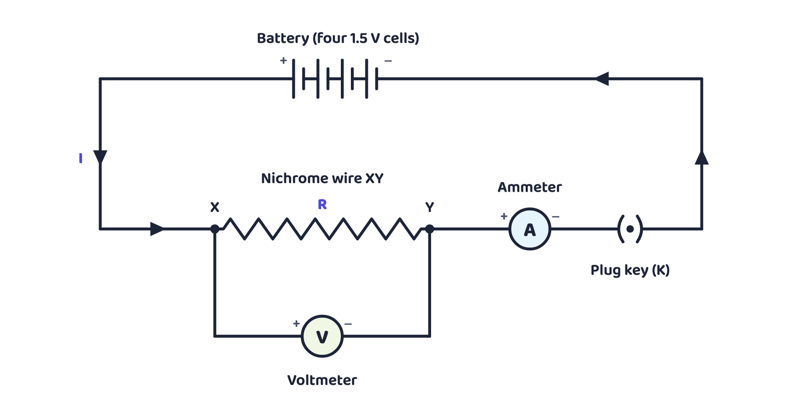
Is there a fixed relationship between the potential difference across a conductor and the current flowing through it? The book explores this with Activity 11.1: a circuit is set up with a nichrome wire XY (about 0.5 m long), an ammeter, a voltmeter and four cells of 1.5 V each (nichrome is an alloy of nickel, chromium, manganese and iron). The readings of current and potential difference are noted using first one cell, then two, three and four cells; the ratio is calculated for each pair, and a graph of against is plotted.
The relationship itself was found in 1827 by the German physicist Georg Simon Ohm (1787-1854), for the current flowing in a metallic wire and the potential difference across its ends.
Every time, the ratio came out to be (approximately) the same constant number. Plotting against gives a straight line passing through the origin: this straight-line, through-the-origin shape is the signature of Ohm’s law.

The potential difference across the ends of a given metallic wire is directly proportional to the current flowing through it, provided its temperature remains the same.
Resistance () is the property of a conductor that resists (opposes) the flow of charge through it. Its SI unit is the ohm, symbol (the Greek letter omega).
From , the current through a resistor is inversely proportional to its resistance: double the resistance and the current is halved, at the same voltage. In many circuits it is useful to change the current without changing the source voltage; a device called a rheostat does exactly this, by letting us change the resistance in the circuit.
A follow-up activity replaced a nichrome wire with a torch bulb’s filament, then a 10 W bulb’s filament, keeping everything else the same. The ammeter reading was different every time: proof that different components resist the flow of current by different amounts.
The current is the motion of electrons through the conductor, but electrons are not completely free to move: as they move among the atoms of the conductor, the atoms’ attraction holds them back and slows them down. This restraining effect on the electrons’ motion is what a conductor’s resistance actually is, and it is why some components let current pass more easily than others.
5 Factors on Which Resistance Depends
An activity varied one thing at a time in a circuit, keeping the source and everything else fixed, and watched the ammeter:
Length doubled
Same thickness, same material, length instead of → ammeter reading became half.
Thickness increased
Same length, same material, but a thicker wire (larger cross-section area) → ammeter reading increased.
Material changed
Same length and area, but copper instead of nichrome → ammeter reading changed again.
Using Ohm’s law on these results shows resistance depends on three things: the conductor’s length, its area of cross-section, and the nature of its material. Precise measurements give:
Electrical resistivity () is a characteristic property of a material: it does not depend on the length or thickness of the wire, only on what the wire is made of (and its temperature).
Metals and alloys have very low resistivity, in the range to : this is exactly why they are good conductors. Insulators like rubber and glass have resistivity as high as to . Both resistance and resistivity change with temperature.
| Material | Resistivity (Ω m) | |
|---|---|---|
| Conductors | Silver | |
| Copper | ||
| Aluminium | ||
| Tungsten | ||
| Nickel | ||
| Iron | ||
| Chromium | ||
| Mercury | ||
| Manganese | ||
| Alloys | Constantan (Cu + Ni) | |
| Manganin (Cu + Mn + Ni) | ||
| Nichrome (Ni + Cr + Mn + Fe) | ||
| Insulators | Glass | to |
| Hard rubber | to | |
| Ebonite | to | |
| Diamond | to | |
| Paper (dry) |
You are not expected to memorise Table 11.2’s numbers: the book says so itself. You only need to know which group (conductor / alloy / insulator) a value belongs to, and use the given values inside a numerical when they are supplied in the question.
Notice that alloys generally have higher resistivity than the pure metals they are made of, and, just as usefully, alloys do not oxidise (burn) readily even at high temperatures. That is exactly why electrical heating devices like the electric iron and toaster use an alloy (nichrome), not a pure metal, for their heating coils. Two more named uses worth remembering: tungsten is used almost exclusively for bulb filaments, while copper and aluminium are used for electrical transmission lines because of their low resistivity.
Given
(a) V, · (b) V,
Find
Current in each case
How much current will (a) an electric bulb of resistance 1200 Ω, and (b) an electric heater coil of resistance 100 Ω, draw from a 220 V source?
(a) 0.18 A
(b) 2.2 A
Same 220 V source, but the heater draws over ten times more current than the bulb, because its resistance is much lower.
Given
V, A; new V
Find
New current
The potential difference across an electric heater is 60 V when it draws 4 A. What current flows if the p.d. is raised to 120 V?
Step 1: Find R:
Step 2: Use the same R at the new voltage:
Answer: 8 A
Given
m, , diameter m
Find
Resistivity , and identify the metal
Resistance of a 1 m metal wire is 26 Ω at 20°C. If its diameter is 0.3 mm, find its resistivity and identify the metal using Table 11.2.
Step 1: Area:
Step 2: From :
Step 3: Substituting the values gives
Answer: Comparing with Table 11.2, this resistivity matches manganese
Given
Wire 1: length , area , . Wire 2 (same material): length , area
Find
A wire of length and area has resistance 4 Ω. What is the resistance of another wire of the same material with length and area ?
Step 1:
Step 2:
Answer: 1 Ω
Halving the length and doubling the area both reduce resistance: together they cut it to one-quarter.
6 Resistance of a System of Resistors
Real circuits almost always use more than one resistor together. There are exactly two ways to connect them: in series (end to end, one path only) or in parallel (side by side, several paths).
6.1 Resistors in series

An activity confirmed that moving the ammeter to any position around a series loop gives the exact same reading: so in series, the current is the same everywhere in the circuit. A voltmeter then showed that the potential difference across the whole combination equals the sum of the potential differences across each resistor separately:
Given
Lamp , resistor , in series with a 6 V battery
Find
(a) Total resistance, (b) current, (c) p.d. across lamp and resistor
An electric lamp of resistance 20 Ω and a conductor of 4 Ω resistance are connected in series to a 6 V battery.
Step 1: Total resistance:
Step 2: Current: 0.25 A
Step 3: p.d. across lamp: 5 V
Step 4: p.d. across conductor: 1 V
Check: , exactly the battery voltage, as expected.
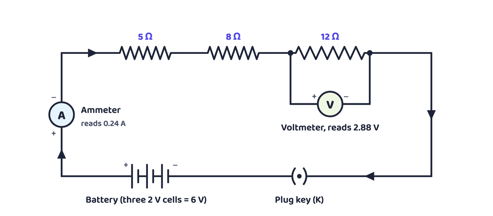
Question 1: Draw the schematic diagram of a battery of three 2 V cells, a 5 Ω, an 8 Ω and a 12 Ω resistor and a plug key, all in series (Figure 3(a)).
Question 2: Redraw it with an ammeter (in series) and a voltmeter across the 12 Ω resistor (Figure 3(b)). Total resistance and the battery gives V, so the ammeter reads 0.24 A and the voltmeter reads 2.88 V.

6.2 Resistors in parallel

This time the activity showed the opposite pattern: the voltmeter reads the same potential difference across the whole combination and across each individual resistor, because all three share the same two end-points, X and Y. But moving the ammeter into each branch in turn gives a different current in each branch, and the total current equals the sum of the branch currents.
Given
, , in parallel on a 12 V battery
Find
(a) Current through each, (b) total current, (c) total resistance
Step 1: Each resistor gets the full 12 V (parallel):
A · A · A
Step 2: Total current: 4 A
Step 3: ⟹ 3 Ω
Given
in parallel; in parallel; the two groups then joined in series; 12 V battery
Find
(a) Total resistance, (b) total current
Step 1: & in parallel: ⟹
Step 2: in parallel: ⟹
Step 3: and are in series: 18 Ω
Step 4: 0.67 A
The method for any mixed network: reduce each parallel (or series) group to one equivalent resistor first, then combine what is left.
6.3 Why your house is wired in parallel, not in series
✓ Parallel (used at home)
- Each appliance gets the full mains voltage, whatever current it individually needs
- Total resistance decreases, so more current can be drawn overall
- If one appliance fails or is switched off, every other appliance keeps working
✗ Series (not used at home)
- A bulb and a heater need very different currents to work properly: they cannot share one series current
- If one component fails, the loop breaks and nothing in the circuit works
Old “fairy lights” for festivals were wired in series: that is exactly why one dead bulb made the whole string go dark, and why the electrician had to test each bulb one by one to find the culprit!
7 Heating Effect of Electric Current
A cell’s chemical energy sets up the current, and the source must keep spending energy to maintain it. In a purely resistive circuit (only resistors connected to a battery, no motor or fan doing useful mechanical work), all of that source energy is eventually given out as heat. This is the heating effect of electric current.
Heat produced in a resistor, , is (i) directly proportional to the square of the current, for a given resistance; (ii) directly proportional to the resistance, for a given current; (iii) directly proportional to the time for which the current flows.
Given
W, W, V
Find
Current and resistance in each case
An electric iron consumes 840 W at maximum heating and 360 W at minimum heating, on a 220 V supply.
(a) Maximum: A; 57.60 Ω
(b) Minimum: A; 134.15 Ω
Given
J, , s
Find
Potential difference
100 J of heat is produced each second in a 4 Ω resistor. Find the p.d. across it.
Step 1: 5 A
Step 2: 20 V
7.1 Practical applications of the heating effect
Heating caused by current is often unwanted: it wastes electrical energy and can damage components. But it is also put to good, deliberate use in several everyday devices:
Electric heater, iron, toaster, oven, kettle
All work directly on Joule’s law: the resistive heating element is the whole point of the device.
Electric bulb
A tungsten filament (melting point 3380°C) is heated by current until it glows. The bulb is filled with chemically inactive nitrogen and argon gas to make the filament last longer. Most of the power still ends up as heat. Only a small part becomes light.
Fuse
A safety device placed in series with an appliance. Its wire (aluminium, copper, iron or lead) is chosen to melt and break the circuit the instant current exceeds a safe, rated value: protecting the appliance from a dangerously high current.
An electric iron rated 1 kW at 220 V draws a current of . Since standard fuse ratings are 1 A, 2 A, 3 A, 5 A and 10 A, the next rating above 4.54 A must be chosen, so a 5 A fuse is used.
8 Electric Power
Power is the rate of doing work, which is the same as the rate at which energy is consumed. The rate at which electric energy is dissipated in a circuit is called electric power.
The SI unit of power is the watt (W): a device consumes 1 W when it carries 1 A of current at a potential difference of 1 V, i.e. . Since the watt is small, a bigger unit, the kilowatt (1000 W), is used in practice.
Electrical energy = power × time. One watt hour (Wh) is the energy used when 1 W of power runs for 1 hour. The commercial (billing) unit of electrical energy is the kilowatt hour (kWh), commonly called a “unit” on your electricity bill.
Electrons are not “used up” or consumed by an electric circuit: the same electrons just keep moving round and round. What we actually pay the electricity company for is the energy spent pushing those electrons through our bulbs, fans and other gadgets.
Given
V, A
Find
Power
An electric bulb is connected to a 220 V supply and draws 0.50 A. Find its power.
110 W
Given
W, 8 h/day, 30 days, ₹3.00 per kWh
Find
Cost of running the refrigerator for 30 days
A 400 W refrigerator runs 8 hours a day. Find the cost of running it for 30 days at ₹3.00 per kWh.
Step 1: Total energy:
Step 2: Cost: ₹288.00
Electricity-bill “cost” numericals always follow the same three steps: (1) find power in watts, (2) convert total energy to kWh (power in kW × time in hours), (3) multiply by the rate per kWh. Getting the W-to-kW conversion right is where most marks are lost.
- Current , unit ampere; conventional direction is opposite to electron flow
- Potential difference , unit volt; ammeter in series, voltmeter in parallel
- Ohm’s law: at constant temperature; resistance , unit ohm
- : resistance grows with length, falls with area, depends on the material (ρ)
- Series: same current, (add resistances). Parallel: same voltage, (add reciprocals)
- Homes are wired in parallel: full voltage to every appliance, one failure doesn’t kill the rest
- Joule’s law: , heat needs current, resistance and time
- Power ; commercial energy unit is the kWh (“unit”), J
- Can I state Ohm’s law and draw the V-I graph it predicts?
- Can I say, without looking, why an ammeter goes in series and a voltmeter goes in parallel?
- Can I write and explain what happens to R if length or area changes?
- Can I derive for series and for parallel?
- Can I explain, in my own words, why household wiring is parallel and not series?
- Can I go from to using Ohm’s law?
- Can I solve a “cost of running an appliance” numerical in kWh, start to finish?